
Edge Solutions
Genset Vibration Monitoring — VMS + ITM Connect
“Know what your genset is telling you: continuous vibration monitoring, analyzed at the edge.”
Genset Vibration Monitoring (VMS)
- Vibration is the first sign of trouble. Catch bearing failures, misalignment, loose components and structural fatigue before they become unplanned downtime.
- Set it up once and it runs on its own: whenever the genset runs, the system measures, analyzes and logs.
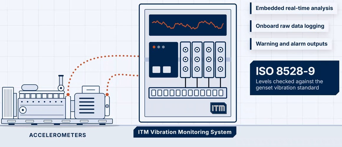
- Overall levels are checked against the ISO 8528-9 guideline values and each order band against limits you set, with configurable warnings and alarms.
- Available as permanent systems, portable kits and rentals, backed by 20+ years of genset monitoring experience.
Genset Vibration Monitoring System
Engine operation, changing load and the environment shake a genset every running hour. Left unwatched, excessive vibration leads to bearing failures, misalignment and structural fatigue, loose components, increased mechanical wear and unplanned downtime. ITM’s Genset Vibration Monitoring System (VMS) is what turns that vibration into an early warning. Accelerometers at the ISO 8528-9 measuring points on the engine and generator feed an ITM edge monitor. The analysis runs on ITM Connect at the edge: it computes the spectrum of every channel, sorts it into order bands, checks overall levels against the ISO 8528-9 guideline values and each band against limits you set, and does three things at once: shows every location live, raises a warning while there is still time to plan the repair, and publishes the results to the systems you already use.
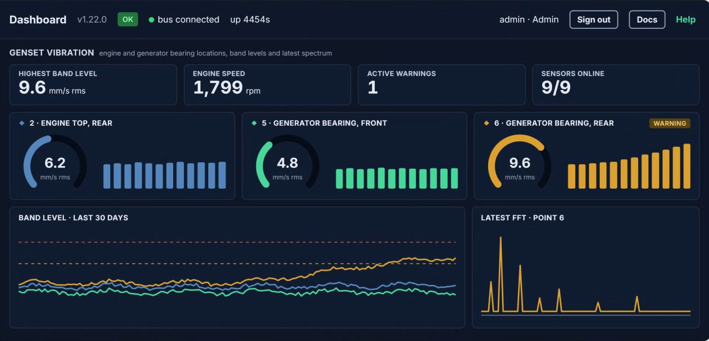
- Multi-channel monitoring — up to 24 or 32 accelerometer channels, depending on the input modules fitted, on one genset or shared across several. Test engineers often add a magnetic pickup to record a speed pulse for further analysis.
- Runs on its own — embedded real-time analysis starts when the system is powered. No operator and no PC are needed for a run to be measured.
- Automated spectral analysis — a Fast Fourier Transform (FFT) on every channel, with RMS and maximum values for each user-defined band.
- Warnings and alarms — configurable warning and alarm levels: the ISO 8528-9 guideline values for overall vibration, and your own limits for every band.
- Onboard logging — raw data, FFTs and the band analysis table are saved for every run, so a warning can be traced back to the waveform.
- System integration — OPC UA, Modbus TCP and MQTT to historians, PLCs and alarm panels, and to cloud dashboards such as AWS and Grafana.
At a glance: Up to 24 or 32 channels, by input module · FFT with RMS and max per order band · ISO 8528-9 guideline values and company-specific band limits · Warning and alarm outputs · Onboard raw data logging · OPC UA, Modbus TCP and MQTT.
From the bearing housing to a planned repair.
The ISO 8528-9 measuring points
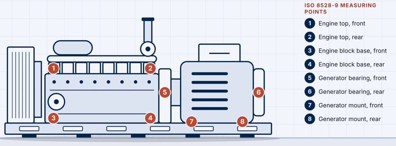
ISO 8528-9 names eight measuring points: the top of the engine at the front and rear, the base of the engine block at the front and rear, the two generator bearing housings and the two generator mounts, each measured in the axial, transverse and vertical directions. With 24 channels, all eight points are measured in three directions; 32 leave room for more.
Catch the climb before the downtime
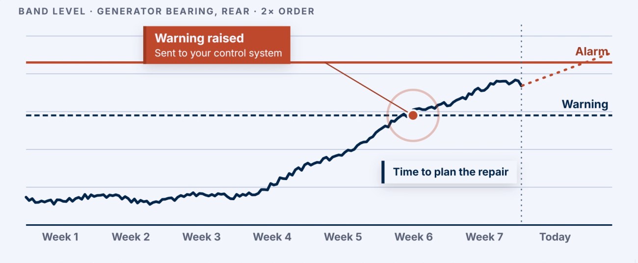
Each run adds a point to the trend for every band. When a level crosses its warning limit, the warning goes to your control system while the genset is still running normally, which turns a slow change into a planned repair. Warning and alarm limits are configurable for every band. The trend shown is illustrative.
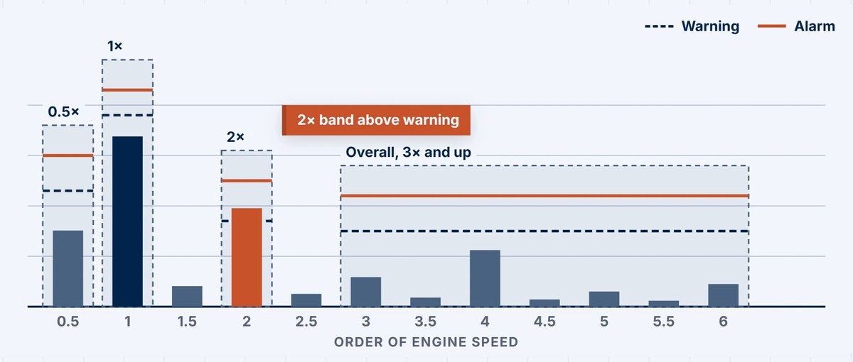
Order-band analysis is the differentiator. An overall vibration number says that something changed. A band says what. Each band is defined by its channel, center order, bandwidth, units (acceleration, velocity or displacement) and its own warning and alarm levels, and a channel can carry several bands, wide or narrow. Because the bands follow engine speed, a rise at half order, first order or second order points to a cause, not just a level. The band limits are your own; the overall level is checked against the ISO 8528-9 guideline values.
Permanent, portable or rental.
How a genset is monitored depends on where it is in its life: on the production line, newly installed, or years into service. The same accelerometers, the same analysis and the same limits apply either way — so the question is not whether to measure vibration, but how long the system needs to stay.
Permanent system
A system that stays with the genset: a stainless steel enclosure with the ITM edge monitor, accelerometers and cables for up to 32 channels, a band-level trend database and warning and alarm indicators.
Portable system and rentals
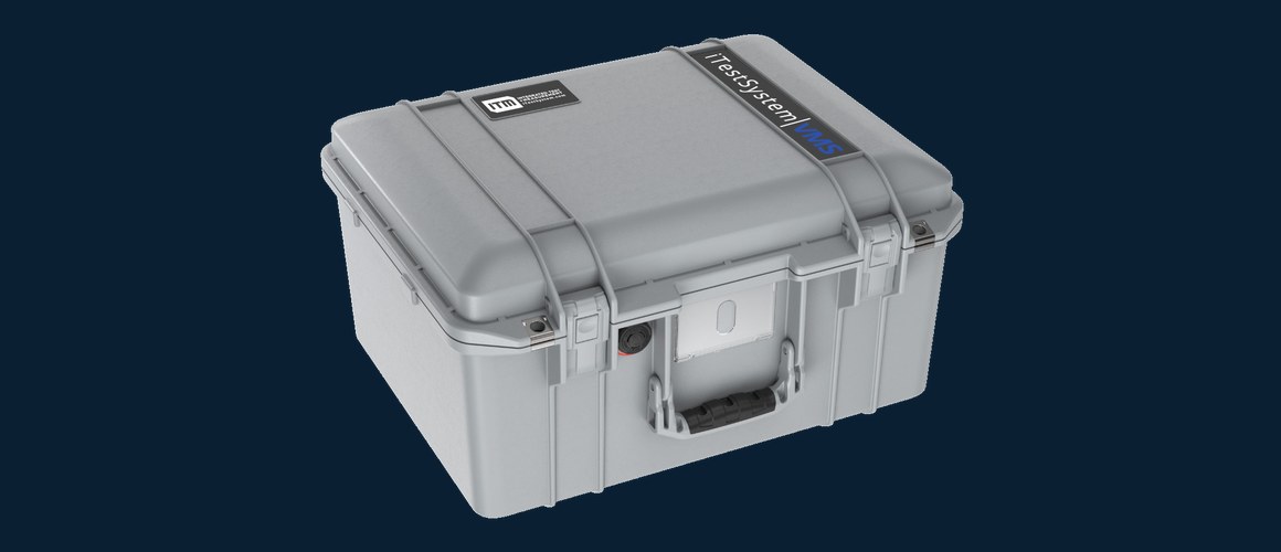
The same monitor and embedded analysis in a rugged carrying case, with accelerometers and cables — to buy or to rent.
For testing more than monitoring — qualifying a new installation to ISO 8528-9, or diagnosing a problem on rotating machinery — ITM also supplies vibration test kits: data acquisition hardware, accelerometers and iTestSystem software in one case.
20+ years of genset monitoring experience, on production lines and installed gensets in the United States and overseas.
Next step: start with a vibration test or rental kit, then scale L1→L5.
Talk to an engineer: (844) 837-8797 · info@iTestSystem.com
Related Edge Solutions resources
-

Wireless Torque. Connected Fleet. Meet ITM at the International WorkBoat Show 2026
Visit ITM at the International WorkBoat Show in New Orleans, Dec. 2–4, 2026, and see how ITM Connect turns shaft torque into insight for one vessel or a fleet.
-
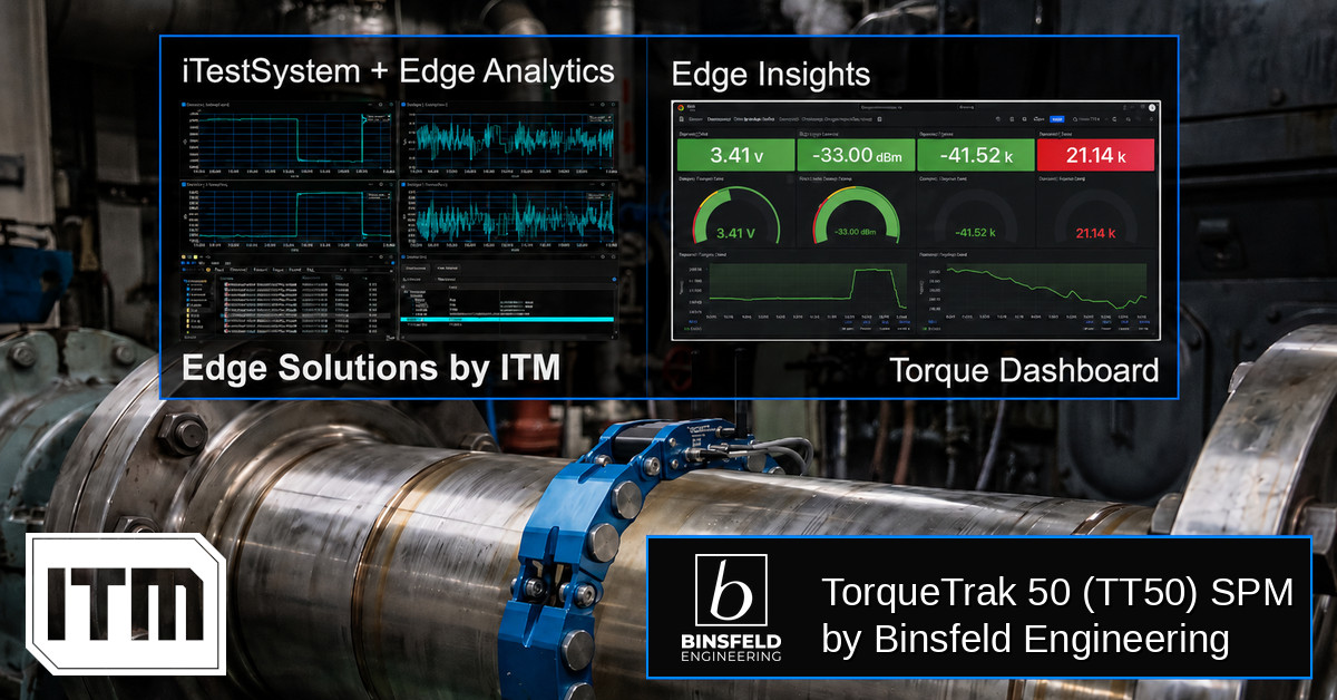
Torque-based Edge Insights: ITM iTestSystem Automated Analytics + Binsfeld TT50
In industrial and marine environments, the drivetrain is often the most critical — and least monitored — part of the system. Rotating shafts transferring torque through gearboxes, couplings, and propellers generate enormous forces that, left unmeasured, become the root cause of unexpected failures, unplanned downtime, and costly maintenance cycles. Traditional torque measurement solutions require shaft…
-
 Ash Hopper Monitoring, Boiler Monitoring, Condition Monitoring, Edge Solutions, Industrial Data Acquisition, industrial IoT, Industrial Monitoring, Power Plant Monitoring, Predictive Maintenance, Recovery Boiler, sootblower monitoring, Strain Gauge Monitoring, Thermocouple Monitoring, vibration monitoring, Wireless Monitoring
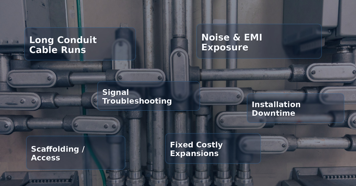
Hardwired vs. Wireless Industrial Monitoring: When Does Wireless Actually Make Sense?
For decades, hardwired data acquisition has been the default standard for industrial monitoring. From strain gauges on structural supports to thermocouples in recovery boilers, running conduit and pulling cable has been considered the “safe”…